Hi Ewout, I get the first warning as well, but ignore this as I know that ESP8266 should be able to run this software. You see in the output that the ESP architecture is recognized (I put that Serial in a a debug).
The second watchdog reset message is something I do not get. From doing other things with the ESP8266 I know that I get that if the ESP8266 needs time to process its WiFi stack procesing and it does not get enough time to do it as it is working on user programs.
I do run the library not in that location but in my sketch directory together with my other libraries.
Are you only running the lmic stack, or also doing WiFi or other work?
I see that after the wdt that the stack resets again, and see that it tries to read somehing from the rfm95 chip. Maybe re-check connections to the RFM95.
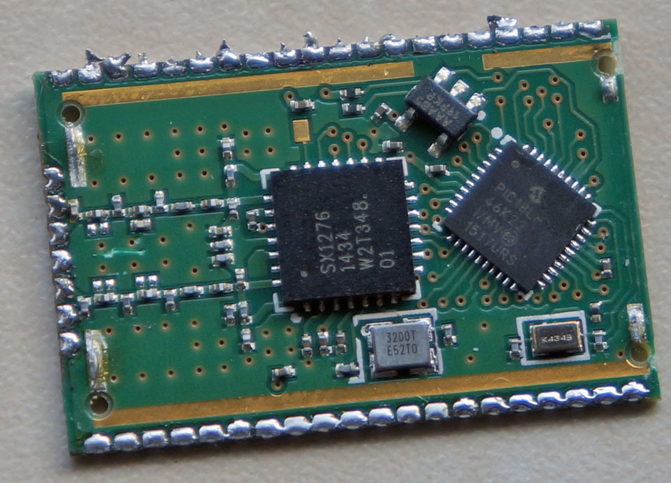
Hi @Ewoud - just to let you know you’re not alone I have a NodeMCU ESP8266 wired up to a bare SX1276 and get a very similar error. Have to triple-check my wiring and try another module just to make sure it’s no hardware snafu.
Comparing the RFM95 and SX1276 I do notice there are RXEN/TXEN pins I haven’t wired in. I hard wired them to switch to RX mode to wake the chip up, but to no avail.
All my wiring checks out OK, so may need to wire up the other bare SX1276 I have lying around.
Could check only now. I am using a sx1276 (nicerf) but not the rfm95 (will check setup with the rfm later to see if this fixes it). In config.h checked if it is setup ok; #define CFG_eu868 1
//#define CFG_us915 1
//#define CFG_sx1272_radio 1 #define CFG_sx1276_radio 1
Will make a library setup within sketch dir and test also with the rfm95 later on. maybe its wiring with the nicerf module (or the module itself) thats not working.
Used a RFM95 instead of the nicerf (not so nice after all;) and boots up now;
hal_init: ESP architecture
os_init() finished
LMIC_reet() finished
LMIC_setSession() finished
LMICsetAddrMode() finished
Init done
Time: 0
Send, txCnhl: 0
Opmode check: ok
I think you mean DIO2 instead of DIO3. However, in order to get the node stable on a USB power adapter (and not on my Serial port) I did connect DIO2 of the RFM95 to D3/GPIO3 on the ESP and connected both of them with a 10K resistor to VCC 3.3V.
I need to test this further, but it seems to make my ESP node more stable.
However, when programming the NodeMCU board you have to temporarily disconnect the D3 pin otherwise the system will not load the firmware.
you defined your code to use a RFM95W/SX1276 while a RFM92W/SX1272 is connected… to change this, in your .ino change the below line (change into SX1276): #define CFG_sx1272_radio 1
your wiring is incorrect, or module just not working
Thanks for the confirmation of this, BoRRoZ - we’d be hoping to find a way to patch or intercept the firmware on theRN2483. Seems a lost opportunity for some lightweight, low-cost use cases.
Okay, I’ve got it running and first message was sent and received!
Now, the signal is really weak, it doesn’t work anymore if I am more than 300m from the gateway. So I suspect my antenna not to be really working, for now I soldered a 10cm wire to the ANT pin of the RFM95W. Does anyone have suggestions on how to improve this considering the device needs to be as small as possible?
Firstly try to make your antenna 8.6cm long. This is a quarter wavelength at 868MHz. Anything longer or shorter will perform worse.
What you can do to make the antenna more compact is to coil the antenna (helical antenna), by winding it around something like a pencil. This will however perform a little less good, but is a good compromise. Similar antennas are commonly used and available for 433MHz here.
 I have a NodeMCU ESP8266 wired up to a bare SX1276 and get a very similar error. Have to triple-check my wiring and try another module just to make sure it’s no hardware snafu.
 (still waiting on a part for my own)…